NCERT Solutions for Class 12 Physics Chapter 6 Electromagnetic Induction is a study material designed for students pursuing science in their senior secondary education. The chapter explores the principles and applications of electromagnetic induction, and the solutions are structured in a concise and simple manner, making it easy for students to understand the concepts and score good marks in their exams.
The NCERT Solutions for Class 12 Physics Chapter 6 Electromagnetic Induction covers various topics such as Faraday’s law, Lenz’s law, self and mutual induction, AC generator, transformer, and many more. These concepts are crucial for students who plan to pursue further studies in physics, as it provides a strong foundation in the subject. By the end of the course, students will have a thorough understanding of the principles and applications of electromagnetic induction, which will be useful in their future studies and career.
Electromagnetic Induction NCERT Solutions for Class Physics Chapter 6
Q1 :Predict the direction of induced current in the situations described by the following Figs. 6.15(a) to (f ).
(a)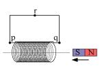
(b)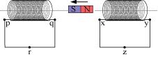
(c)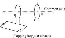
(d)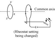
(e)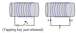
(f)
Answer :
The direction of the induced current in a closed loop is given by Lenz’s law. The given pairs of figures show the direction of the induced current when the North pole of a bar magnet is moved towards and away from a closed loop respectively.
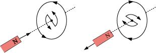
Using Lenz’s rule, the direction of the induced current in the given situations can be predicted as follows:
(a) The direction of the induced current is along qrpq.
(b) The direction of the induced current is along prqp.
(c) The direction of the induced current is along yzxy.
(d) The direction of the induced current is along zyxz.
(e) The direction of the induced current is along xryx.
(f) No current is induced since the field lines are lying in the plane of the closed loop.
Q2 :Use Lenz’s law to determine the direction of induced current in the situations described by Fig. 6.16:
(a) A wire of irregular shape turning into a circular shape;
(b) A circular loop being deformed into a narrow straight wire.
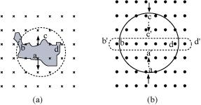
Answer :
According to Lenz’s law, the direction of the induced emf is such that it tends to produce a current that opposes the change in the magnetic flux that produced it.
(a) When the shape of the wire changes, the flux piercing through the unit surface area increases. As a result, the induced current produces an opposing flux. Hence, the induced current flows along adcb.
(b) When the shape of a circular loop is deformed into a narrow straight wire, the flux piercing the surface decreases. Hence, the induced current flows along
Q3 :A long solenoid with 15 turns per cm has a small loop of area 2.0 cm2 placed inside the solenoid normal to its axis. If the current carried by the solenoid changes steadily from 2.0 A to 4.0 A in 0.1 s, what is the induced emf in the loop while the current is changing?
Answer :
Number of turns on the solenoid = 15 turns/cm = 1500 turns/m
Number of turns per unit length, n = 1500 turns
The solenoid has a small loop of area, A = 2.0 cm2 = 2 × 10⁻⁴ m2
Current carried by the solenoid changes from 2 A to 4 A.
Change in current in the solenoid, di = 4 – 2 = 2 A
Change in time, dt = 0.1 s
Induced emf in the solenoid is given by Faraday’s law as:
![]()
Where,
Φ = Induced flux through the small loop
= BA … (ii)
B = Magnetic field
=![]()
μ0= Permeability of free space
= 4π×10-7 H/m
Hence, equation (i) reduces to:
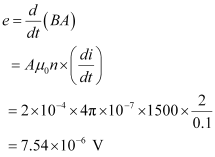
Hence, the induced voltage in the loop is 7.54 x 10⁻⁶ V
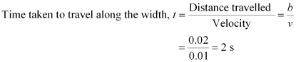
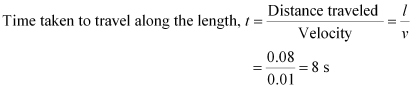
Q4 :A rectangular wire loop of sides 8 cm and 2 cm with a small cut is moving out of a region of uniform magnetic field of magnitude 0.3 T directed normal to the loop. What is the emf developed across the cut if the velocity of the loop is 1 cm s-1 in a direction normal to the (a) longer side, (b) shorter side of the loop? For how long does the induced voltage last in each case?
Answer :
Length of the rectangular wire, l = 8 cm = 0.08 m
Width of the rectangular wire, b = 2 cm = 0.02 m
Hence, area of the rectangular loop,
A = lb
= 0.08 × 0.02
= 16 × 10-4 m2
Magnetic field strength, B = 0.3 T
Velocity of the loop, v = 1 cm/s = 0.01 m/s
(a) Emf developed in the loop is given as:
e = Blv
= 0.3 × 0.08 × 0.01 = 2.4 × 10⁻⁴ V
Hence, the induced voltage is 2.4 × 10⁻⁴ V which lasts for 2 s.
(b) Emf developed, e = Bbv
= 0.3 × 0.02 × 0.01 = 0.6 × 10⁻⁴ V
Hence, the induced voltage is 0.6 × 10⁻⁴ V which lasts for 8 s.
Q5 :A 1.0 m long metallic rod is rotated with an angular frequency of 400 rad
s-1 about an axis normal to the rod passing through its one end. The other end of the rod is in contact with a circular metallic ring. A constant and uniform magnetic field of 0.5 T parallel to the axis exists everywhere. Calculate the emf developed between the centre and the ring.
Answer :
Length of the rod, l = 1 m
Angular frequency,ω = 400 rad/s
Magnetic field strength, B = 0.5 T
One end of the rod has zero linear velocity, while the other end has a linear velocity of lω.
Average linear velocity of the rod,![]()
Emf developed between the centre and the ring,
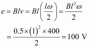
Hence, the emf developed between the centre and the ring is 100 V.
Q6 :A horizontal straight wire 10 m long extending from east to west is falling with a speed of 5.0 m s-1, at right angles to the horizontal component of the earth’s magnetic field, 0.30 x 10⁻⁴ Wb m-2.
(a) What is the instantaneous value of the emf induced in the wire?
(b) What is the direction of the emf?
(c) Which end of the wire is at the higher electrical potential?
Answer :
Length of the wire, l = 10 m
Falling speed of the wire, v = 5.0 m/s
Magnetic field strength, B = 0.3 × 10⁻⁴ Wb m-2
(a) Emf induced in the wire,
e = Blv
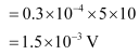
(b) Using Fleming’s right hand rule, it can be inferred that the direction of the induced emf is from West to East.
(c) The eastern end of the wire is at a higher potential.
Q7 :Current in a circuit falls from 5.0 A to 0.0 A in 0.1 s. If an average emf of 200 V induced, give an estimate of the self-inductance of the circuit.
Answer :
Initial current, I1 = 5.0 A
Final current, I2 = 0.0 A
Change in current,dI = I1 – I2 = 5 A
Time taken for the change, t = 0.1 s
Average emf, e = 200 V
For self-inductance (L) of the coil, we have the relation for average emf as:
e=L![]()
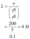
e = L
Hence, the self induction of the coil is 4 H.
Q8 :A pair of adjacent coils has a mutual inductance of 1.5 H. If the current in one coil changes from 0 to 20 A in 0.5 s, what is the change of flux linkage with the other coil?
Answer :
Mutual inductance of a pair of coils, µ = 1.5 H
Initial current, I1 = 0 A
Final current I2 = 20 A
Change in current,dI = I2 – I1 = 20 – 0 =20 A
Time taken for the change, t = 0.5 s
Induced emf,![]()
Where is the change in the flux linkage with the coil.
Emf is related with mutual inductance as:
![]()
Equating equations (1) and (2), we get

Hence, the change in the flux linkage is 30 Wb.