NCERT Solutions for Class 12 Physics Chapter 3, Current Electricity explains how electric charges flow through conductors and how different laws govern this flow. It starts with the definition of current and current density, then introduces Ohm’s law (V = IR) and explains the concept of resistivity and how it depends on material and temperature. The chapter also shows how resistors combine in series and parallel, and how electrical power (P = VI, I²R, V²/R) is calculated. It explains cells, EMF, internal resistance, and how cells are arranged in series or parallel. For complex circuits, Kirchhoff’s rules are used. Finally, it covers practical methods like the Wheatstone bridge, meter bridge, and potentiometer for measuring resistance and potential differences. In short, the chapter gives the principles, formulas, and techniques needed to solve circuit problems and understand how electricity works in real life.
Current Electricity NCERT Solutions for Chapter 3 – Class 12 Physics
Q1 :The storage battery of a car has an emf of 12 V. If the internal resistance of the battery is 0.4Ω, what is the maximum current that can be drawn from the battery?
Answer :
Emf of the battery, E = 12 V
Internal resistance of the battery, r = 0.4 Ω
Maximum current drawn from the battery = I
According to Ohm’s law,
The maximum current drawn from the given battery is 30 A.
Q2 :A battery of emf 10 V and internal resistance 3 Ω is connected to a resistor. If the current in the circuit is 0.5 A, what is the resistance of the resistor? What is the terminal voltage of the battery when the circuit is closed?
Answer :
Emf of the battery, E = 10 V
Internal resistance of the battery, r = 3 Ω
Current in the circuit, I = 0.5 A
Resistance of the resistor = R
The relation for current using Ohm’s law is,
Terminal voltage of the resistor = V
According to Ohm’s law,
V = IR
= 0.5 × 17
= 8.5 V
Therefore, the resistance of the resistor is 17 Ω and the terminal voltage is
8.5 V.
Q3 :At room temperature (27.0 °C) the resistance of a heating element is 100 Ω. What is the temperature of the element if the resistance is found to be 117 Ω, given that the temperature coefficient of the material of the resistor is
Answer :
Room temperature, T = 27°C
Resistance of the heating element at T, R = 100 Ω
Let T1 is the increased temperature of the filament.
Resistance of the heating element at T1, R1 = 117 Ω
Temperature co-efficient of the material of the filament,
Therefore, at 1027°C, the resistance of the element is 117 Ω.
Q4 :A negligibly small current is passed through a wire of length 15 m and uniform cross-section 6.0 x 10⁻⁷ m2, and its resistance is measured to be 5.0 Ω. What is the resistivity of the material at the temperature of the experiment?
Answer :
Length of the wire, l =15 m
Area of cross-section of the wire, a = 6.0 × 10 – 7 m2
Resistance of the material of the wire, R = 5.0 Ω
Resistivity of the material of the wire = ρ
Resistance is related with the resistivity as
Therefore, the resistivity of the material is 2 × 10 – 7 Ω m.
Q5 :A silver wire has a resistance of 2.1 Ω at 27.5 °C, and a resistance of 2.7 Ω at 100 °C. Determine the temperature coefficient of resistivity of silver.
Answer :
Temperature, T1 = 27.5°C
Resistance of the silver wire at T1, R1 = 2.1 Ω
Temperature, T2 = 100°C
Resistance of the silver wire at T2, R2 = 2.7 Ω
Temperature coefficient of silver = α
It is related with temperature and resistance as
Therefore, the temperature coefficient of silver is 0.0039°C-1.
Q6 :Aheating element using nichrome connected to a 230 V supply draws an initial current of 3.2 A which settles after a few seconds toa steady value of 2.8 A. What is the steady temperature of the heating element if the room temperature is 27.0 °C? Temperature coefficient of resistance of nichrome averaged over the temperature range involved is 1.70 x 10⁻⁴ °C -1.
Answer :
Supply voltage, V = 230 V
Initial current drawn, I1 = 3.2 A
Initial resistance = R1, which is given by the relation,
Steady state value of the current, I2 = 2.8 A
Resistance at the steady state = R2, which is given as
![]()
Temperature co-efficient of nichrome, α = 1.70 × 10 – 4 °C – 1
Initial temperature of nichrome, T1= 27.0°C
Study state temperature reached by nichrome = T2
T2 can be obtained by the relation for α,
Therefore, the steady temperature of the heating element is 867.5°C
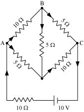
Q7 :Determine the current in each branch of the network shown in fig 3.30:
Answer :
Current flowing through various branches of the circuit is represented in the given figure.
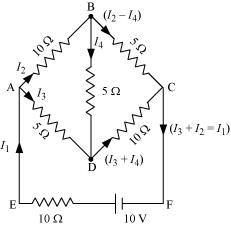
I1 = Current flowing through the outer circuit
I2 = Current flowing through branch AB
I3 = Current flowing through branch AD
I2 – I4 = Current flowing through branch BC
I3 + I4 = Current flowing through branch CD
I4 = Current flowing through branch BD
For the closed circuit ABDA, potential is zero i.e.,
10I2 + 5I4 – 5I3 = 0
2I2 + I4 – I3 = 0
I3 = 2I2 + I4 … (1)
For the closed circuit BCDB, potential is zero i.e.,
5(I2 – I4) – 10(I3 +I4) – 5I4 = 0
5I2 + 5I4 – 10I3 – 10I4 – 5I4 = 0
5I2 – 10I3 – 20I4 = 0
I2 = 2I3 + 4I4 … (2)
For the closed circuit ABCFEA, potential is zero i.e.,
– 10 + 10 (I1) + 10(I2) + 5(I2 – I4) = 0
10 = 15I2 + 10I1 – 5I4
3I2 + 2I1 – I4 = 2 … (3)
From equations (1) and (2), we obtain
I3 = 2(2I3 + 4I4) + I4
I3 = 4I3 + 8I4 + I4
– 3I3 = 9I4
– 3I4 = + I3 … (4)
Putting equation (4) in equation (1), we obtain
I3 = 2I2 + I4
– 4I4 = 2I2
I2 = – 2I4 … (5)
It is evident from the given figure that,
I1 = I3 + I2 … (6)
Putting equation (6) in equation (1), we obtain
3I2 +2(I3 + I2) – I4 = 2
5I2 + 2I3 – I4 = 2 … (7)
Putting equations (4) and (5) in equation (7), we obtain
5( – 2 I4) + 2( – 3 I4) – I4 = 2
– 10I4 – 6I4 – I4 = 2
17I4 = – 2
![]()
Equation (4) reduces to
I3 = – 3(I4)
Therefore, current in branch ![]()
In branch BC =6/17 A
In branch CD =-4/17 A
In branch AD= 6/17 A
In branch BD =-2/17 A
Total current =4/17 + 6/17 +(-4)/17 + 6/17 + (-2) /17
= 10/17 A
Q8 :A storage battery of emf 8.0 V and internal resistance 0.5 Ω is being charged by a 120 V dc supply using a series resistor of 15.5 Ω. What is the terminal voltage of the battery during charging? What is the purpose of having a series resistor in the charging circuit?
Answer :
Emf of the storage battery, E = 8.0 V
Internal resistance of the battery, r = 0.5 Ω
DC supply voltage, V = 120 V
Resistance of the resistor, R = 15.5 Ω
Effective voltage in the circuit = V1
R is connected to the storage battery in series. Hence, it can be written as
V1 = V – E
V1 = 120 – 8 = 112 V
Current flowing in the circuit = I, which is given by the relation,
Voltage across resistor R given by the product, IR = 7 × 15.5 = 108.5 V
DC supply voltage = Terminal voltage of battery + Voltage drop across R
Terminal voltage of battery = 120 – 108.5 = 11.5 V
A series resistor in a charging circuit limits the current drawn from the external source. The current will be extremely high in its absence. This is very dangerous.
Q9 :The number density of free electrons in a copper conductor estimated in Example 3.1 is 8.5 x 1028 m-3. How long does an electron take to drift from one end of a wire 3.0 m long to its other end? The area of cross-section of the wire is 2.0 x 10⁻⁶ m2 and it is carrying a current of 3.0 A.
Answer :
Number density of free electrons in a copper conductor, n = 8.5 × 1028 m – 3 Length of the copper wire, l = 3.0 m
Area of cross-section of the wire, A = 2.0 × 10⁻⁶ m2
Current carried by the wire, I = 3.0 A, which is given by the relation,
I = nAeVd
Where,
e = Electric charge = 1.6 × 10 – 19 C
Vd = Drift velocity![]()
Therefore, the time taken by an electron to drift from one end of the wire to the other is 2.7 × 10⁴ s.